Dear all,
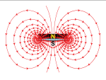
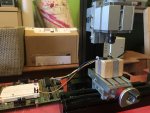
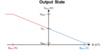
I have an idea following up my little line follower projects from earlier. I would like to achieve similar functionality using hall sensors and small magnets. I have tested the physical feasibility and I'm now thinking about the algorithms. I have built a 'sensor' from three DRV5053 hall sensors. The advantage of those is they are bidirectional i.e. they are able to measure S and N pole of magnets. They produce a voltage of 1.0V when there is no magnetic field present and deviate up for S pole and down for N pole magnet. For my situation this is important, as I need to maintain 'magnet line' following capability while decoding 'messages' coded with N and S pole magnets. Assume S = 1 and N = 0. Most magnets are N. Then, S magnet is a 'start condition' followed by 4 bit code encoded with the following magnets. Gives me 16 possible messages encoded in the road.
I have been sketching on napkins and various other surfaces ideas for calculating where the line is from this for a few days now, but every time I come up with something, I discover it not to work for both polarities of magnets at the same time. Intuitively, it feels this should be a simple task, but somehow I cannot come up with a solution. [I used completely different idea for the optical line follower back then, so this is of no use.]
The ADC_8 value of no magnetic field is about 55 with the supply of 4.5V. It will be around 100 in the final application or 125 if I use FRV2048. My best solution, albeit working with one pole only, is as follows.
Assume LEFT sensor is 0, CENTRE sensor is 1 and RIGHT sensor is 2. Read all sensors and multiply the results with 0 for LEFT, 1000 for CENTRE and 2000 for RIGHT. Add up the result and divide with the sum of direct ADC results. This is working and with very good resolution, but is quite math intensive and falls apart if you reverse the field, because now the LEFT sensor should be 2 and the RIGHT sensor should be 1. There are obvious ways of accounting for this, like running ADC twice and then determining if what we are seeing is N or S magnet, but this will take way too much time for the final implementation. Need to find something more efficient.
Maybe you have some time to think about this and come up with a hint to something I'm obviously missing") .
.
Thank you for your time,
Edmunds
I have an idea following up my little line follower projects from earlier. I would like to achieve similar functionality using hall sensors and small magnets. I have tested the physical feasibility and I'm now thinking about the algorithms. I have built a 'sensor' from three DRV5053 hall sensors. The advantage of those is they are bidirectional i.e. they are able to measure S and N pole of magnets. They produce a voltage of 1.0V when there is no magnetic field present and deviate up for S pole and down for N pole magnet. For my situation this is important, as I need to maintain 'magnet line' following capability while decoding 'messages' coded with N and S pole magnets. Assume S = 1 and N = 0. Most magnets are N. Then, S magnet is a 'start condition' followed by 4 bit code encoded with the following magnets. Gives me 16 possible messages encoded in the road.
I have been sketching on napkins and various other surfaces ideas for calculating where the line is from this for a few days now, but every time I come up with something, I discover it not to work for both polarities of magnets at the same time. Intuitively, it feels this should be a simple task, but somehow I cannot come up with a solution. [I used completely different idea for the optical line follower back then, so this is of no use.]
The ADC_8 value of no magnetic field is about 55 with the supply of 4.5V. It will be around 100 in the final application or 125 if I use FRV2048. My best solution, albeit working with one pole only, is as follows.
Assume LEFT sensor is 0, CENTRE sensor is 1 and RIGHT sensor is 2. Read all sensors and multiply the results with 0 for LEFT, 1000 for CENTRE and 2000 for RIGHT. Add up the result and divide with the sum of direct ADC results. This is working and with very good resolution, but is quite math intensive and falls apart if you reverse the field, because now the LEFT sensor should be 2 and the RIGHT sensor should be 1. There are obvious ways of accounting for this, like running ADC twice and then determining if what we are seeing is N or S magnet, but this will take way too much time for the final implementation. Need to find something more efficient.
Maybe you have some time to think about this and come up with a hint to something I'm obviously missing
.Thank you for your time,
Edmunds