Hemi345
Senior Member
My daughter is really enjoying model rocketry. She's built two rockets so far and is curious to know how high they are flying. PICAXE project time!
I searched around the web and found a few custom-built altimeters, mostly on the Arduino platform. After some research, I decided on the following components:
PICAXE 14M2
Freescale MPL3115A2 pressure sensor
Microchip 24FC512 EEPROM
ST M41T62LC6F real time clock
Supporting components are:
Maxwell BCAP0005 2.7V, 5F supercapacitor
Microchip MCP16251 sync boost regulator
Four 'super' red LEDs
2 momentary push buttons
Requirements for this project are:
- small/lightweight - so it can be used on small rockets
- adaptability - so it can be attached ghetto-style to the side of rockets without a payload section
- easy to use
- quick charge time - no one likes to wait!
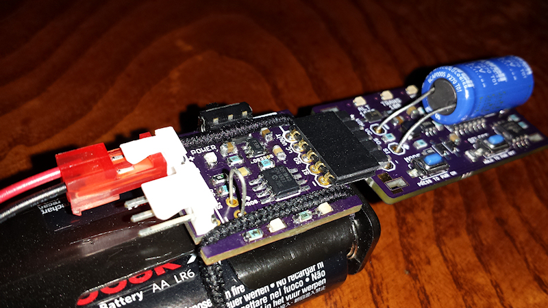
I first designed a simple little supercapacitor charger based on an 08M2 to charge the 5F supercap using 3AA (alkaline) or 4AA (NiMH). It will charge it from about 1V to 2.5V in about 2.5 minutes.
Charger charging the supercap:
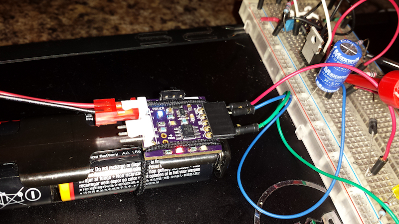
(with a bunch of additional stuff plugged into the breadboard to make it look complicated/awesome)
Using Maxim Integrated's super capacitor calculator, I set about finding how long the supercap would last at certain discharge current levels. Since the voltage of a supercap immediately starts declining as it's discharged, I would only get 2.5V for maybe a minute with a 2mA draw. All the major components will run on about 2V, but this means runtime is going to be really short unless I boosted the voltage. Enter the MCP16251 synchronous boost regulator. I configured a 2.7Vout using the feedback resistor divider. This should allow all the components on the I2C bus to run at 400kHz and allow the supercap to discharge down to 0.8V! According to Maxim's calculator, that should give me about 28 minutes of run time @ 5mA (worst case senario) - plenty of time for a few flights. And since it takes very little time to charge the supercap, we can plug it in to charge between flights, if needed, while we repack the parachute and switch rocket engines.
Since nearly all the devices are SMD, I didn't have the opportunity to breadboard most of it. I did solder up a spare MCP16251 and inductor on a breakout board to check current consumption while driving a DIP-based 14M2 and a few LEDs for my own amusement.
Then I worked up a schematic and the board layout using Cadsoft Eagle PCB. I used the PICAXE library I built for the SMD version of the 14M2 and I also created footprints for the MPL3115A2, M41T62 RTC, and the 4.7uH inductor. The rest of the components are pretty standard and were pulled from the libraries that come with Eagle or that I downloaded (BTW, Sparkfun has a great Eagle library).
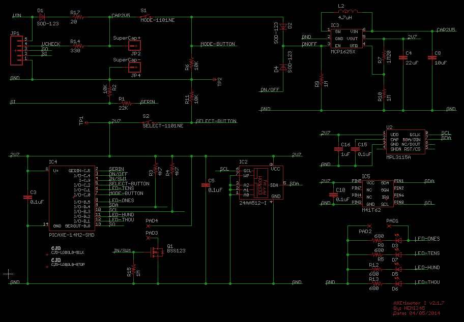
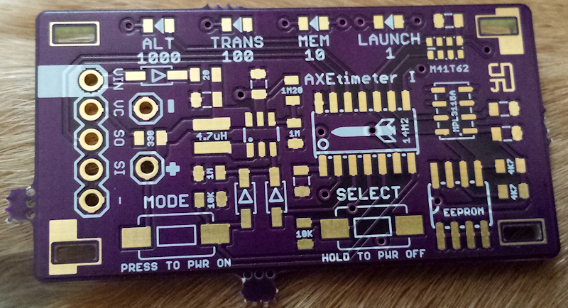
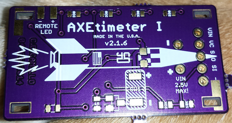
After many revisions and layout changes, I finally settled on a design and sent it off to OSHpark.com.
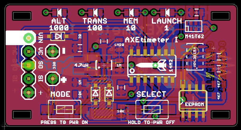
Here's what OSHpark said my board should look like:
The board measures 1.70x0.90 inches (43.18x22.89 mm)
A couple weeks later I had three shiny PCBs waiting to be soldered up.
I used the skillet method of soldering on this PCB since 95% of the components are on the top side.
It's inadvisable to toast bread or fry eggs in the same pan while doing this... it makes them tastes weird.
Here's a pic of it in the skillet with the paste on and components placed and warming up:
Hot out of the skillet - waiting for it to cool down:
I soldered the resistors for the LEDs, programming/charging header and a ceramic cap on the back side of the board by hand (nearly all the passive components are 0805 sized).
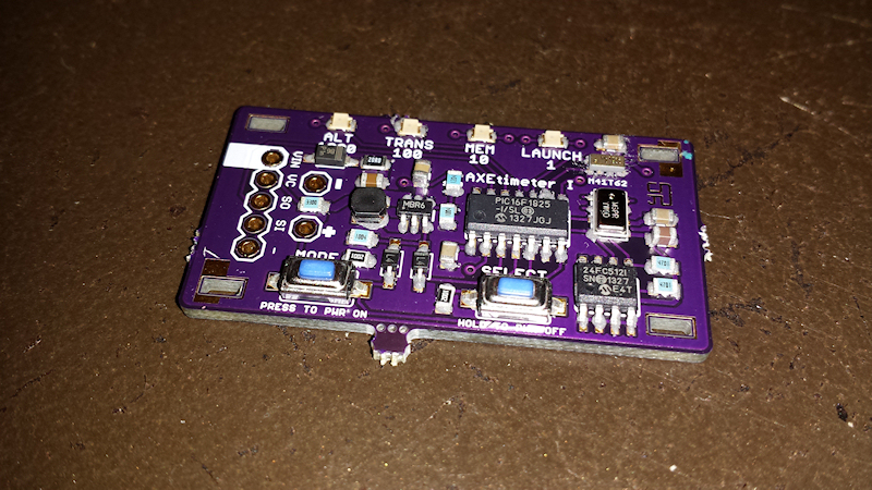
The supercap jammed through the holes and powered up:

IT'S ALIVE!
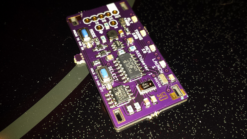
Charging the AXEtimeter with the AXEtimeter PnC (Plug 'n Charge) patent pending. You can see how the supercap will eventually be soldered into place - it's more aerodynamic this way:
Since there isn't a manual power switch, I've left the supercap unsoldered till I get the program completely ironed out. I don't have a way to power OFF the device except through the software. For now if I screw up the interrupt routine that handles that, I can just disconnect the cap. In the future with the cap soldered into place, if I mess up a program edit, I can simply hookup the programming cable and try to program it. Doing this resets all the pins, putting the pin I'm using to enable the voltage regulator back to an input (basically low) and that will power it off. The power off procedure has been really solid, so I'm just about to solder the cap in place. Another 'feature' is when I want to program it, I have to hold the MODE button down to keep the PICAXE powered up while it's being programmed. No big deal really and won't affect its normal operation.
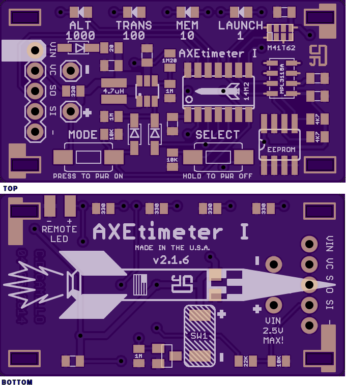
What's SW1 for on the bottom of the board and why is it connected to an input-only pin?
I'm not sure what we'll use that for yet, but it seemed like a good idea to break that pin out and give it the capability of driving an n-channel mosfet using a cool trick with the integrated pullup command. Maybe use it to simply light another LED or trigger deployment of the parachute or....
Why did I choose those components?
The 14M2 is a great little chip. First, it's in a space saving narrow SOIC package, has enough pins for most projects I've designed, and now has 2 program slots, thanks to PE6. Too bad it covered up the little rocket I put on the silkscreen beneath it.
The MPL3115A2 pressure sensor has an altimeter mode that will output the elevation in meters. Not only that, but it also has a maximum altitude register that records the ... well, maximum altitude since the device was last powered up. This frees up program space since I don't need to take the pressure data and calculate the altitude. I only need to program the math to subtract launch altitude from the max altitude to get how high the rocket flew. It'll take 100 readings per second in 'one shot mode'... most dataloggers I saw use about a 20-30hz resolution. The device uses I2C, so it fits in well with the rest of the components. The little hole on the IC needs to be shielded as it's sensitive to light... the supercap placed over the top should do the trick.
Have you scrolled up to look for the little rocket on the silkscreen beneath the 14M2 yet?
The 24FC512 EEPROM has 512Kb of space which should be enough to store a few flights. It uses I2C and I chose the 'FC' model since it'll continue to run at full bus speed (400kHz) if the voltage dips below 2.5V. It will be used to store flight data which will be easily uploaded for use in Excel. This will give us the capability to log multiple flights without having to download the data from the device after each flight.
The M41T62 RTC is a tiny sucker. This saved board space and weight and has an integrated crystal - bonus! But more importantly, it will record hundredths of seconds. This resolution will work well to capture flight time with the rest of the flight data so we can see exactly how many seconds the flight lasted, when the apex occurred, calculate velocity and speed, etc once the data is uploaded.
A super capacitor? I wanted to try something different by going with the supercap because 1) I saw another altimeter that used one and it seemed like a cool idea, 2) they can be charged really fast and many more times than a conventional battery, 3) they're pretty light and compact, 4) I found some in a cool blue color and my daughter likes blue. 5) 5F seemed like a good starting point because I didn't have a good idea on current draw for this project. Now that I see how efficient the AxEtimeter is, a smaller .5F or 1F would be plenty.
%101011 continued...
I searched around the web and found a few custom-built altimeters, mostly on the Arduino platform. After some research, I decided on the following components:
PICAXE 14M2
Freescale MPL3115A2 pressure sensor
Microchip 24FC512 EEPROM
ST M41T62LC6F real time clock
Supporting components are:
Maxwell BCAP0005 2.7V, 5F supercapacitor
Microchip MCP16251 sync boost regulator
Four 'super' red LEDs
2 momentary push buttons
Requirements for this project are:
- small/lightweight - so it can be used on small rockets
- adaptability - so it can be attached ghetto-style to the side of rockets without a payload section
- easy to use
- quick charge time - no one likes to wait!
I first designed a simple little supercapacitor charger based on an 08M2 to charge the 5F supercap using 3AA (alkaline) or 4AA (NiMH). It will charge it from about 1V to 2.5V in about 2.5 minutes.
Charger charging the supercap:
(with a bunch of additional stuff plugged into the breadboard to make it look complicated/awesome)
Using Maxim Integrated's super capacitor calculator, I set about finding how long the supercap would last at certain discharge current levels. Since the voltage of a supercap immediately starts declining as it's discharged, I would only get 2.5V for maybe a minute with a 2mA draw. All the major components will run on about 2V, but this means runtime is going to be really short unless I boosted the voltage. Enter the MCP16251 synchronous boost regulator. I configured a 2.7Vout using the feedback resistor divider. This should allow all the components on the I2C bus to run at 400kHz and allow the supercap to discharge down to 0.8V! According to Maxim's calculator, that should give me about 28 minutes of run time @ 5mA (worst case senario) - plenty of time for a few flights. And since it takes very little time to charge the supercap, we can plug it in to charge between flights, if needed, while we repack the parachute and switch rocket engines.
Since nearly all the devices are SMD, I didn't have the opportunity to breadboard most of it. I did solder up a spare MCP16251 and inductor on a breakout board to check current consumption while driving a DIP-based 14M2 and a few LEDs for my own amusement.
Then I worked up a schematic and the board layout using Cadsoft Eagle PCB. I used the PICAXE library I built for the SMD version of the 14M2 and I also created footprints for the MPL3115A2, M41T62 RTC, and the 4.7uH inductor. The rest of the components are pretty standard and were pulled from the libraries that come with Eagle or that I downloaded (BTW, Sparkfun has a great Eagle library).
After many revisions and layout changes, I finally settled on a design and sent it off to OSHpark.com.
Here's what OSHpark said my board should look like:
The board measures 1.70x0.90 inches (43.18x22.89 mm)
A couple weeks later I had three shiny PCBs waiting to be soldered up.
I used the skillet method of soldering on this PCB since 95% of the components are on the top side.
It's inadvisable to toast bread or fry eggs in the same pan while doing this... it makes them tastes weird.
Here's a pic of it in the skillet with the paste on and components placed and warming up:
Hot out of the skillet - waiting for it to cool down:
I soldered the resistors for the LEDs, programming/charging header and a ceramic cap on the back side of the board by hand (nearly all the passive components are 0805 sized).
The supercap jammed through the holes and powered up:
IT'S ALIVE!
Charging the AXEtimeter with the AXEtimeter PnC (Plug 'n Charge) patent pending. You can see how the supercap will eventually be soldered into place - it's more aerodynamic this way:
Since there isn't a manual power switch, I've left the supercap unsoldered till I get the program completely ironed out. I don't have a way to power OFF the device except through the software. For now if I screw up the interrupt routine that handles that, I can just disconnect the cap. In the future with the cap soldered into place, if I mess up a program edit, I can simply hookup the programming cable and try to program it. Doing this resets all the pins, putting the pin I'm using to enable the voltage regulator back to an input (basically low) and that will power it off. The power off procedure has been really solid, so I'm just about to solder the cap in place. Another 'feature' is when I want to program it, I have to hold the MODE button down to keep the PICAXE powered up while it's being programmed. No big deal really and won't affect its normal operation.
What's SW1 for on the bottom of the board and why is it connected to an input-only pin?
I'm not sure what we'll use that for yet, but it seemed like a good idea to break that pin out and give it the capability of driving an n-channel mosfet using a cool trick with the integrated pullup command. Maybe use it to simply light another LED or trigger deployment of the parachute or....
Why did I choose those components?
The 14M2 is a great little chip. First, it's in a space saving narrow SOIC package, has enough pins for most projects I've designed, and now has 2 program slots, thanks to PE6. Too bad it covered up the little rocket I put on the silkscreen beneath it.
The MPL3115A2 pressure sensor has an altimeter mode that will output the elevation in meters. Not only that, but it also has a maximum altitude register that records the ... well, maximum altitude since the device was last powered up. This frees up program space since I don't need to take the pressure data and calculate the altitude. I only need to program the math to subtract launch altitude from the max altitude to get how high the rocket flew. It'll take 100 readings per second in 'one shot mode'... most dataloggers I saw use about a 20-30hz resolution. The device uses I2C, so it fits in well with the rest of the components. The little hole on the IC needs to be shielded as it's sensitive to light... the supercap placed over the top should do the trick.
Have you scrolled up to look for the little rocket on the silkscreen beneath the 14M2 yet?
The 24FC512 EEPROM has 512Kb of space which should be enough to store a few flights. It uses I2C and I chose the 'FC' model since it'll continue to run at full bus speed (400kHz) if the voltage dips below 2.5V. It will be used to store flight data which will be easily uploaded for use in Excel. This will give us the capability to log multiple flights without having to download the data from the device after each flight.
The M41T62 RTC is a tiny sucker. This saved board space and weight and has an integrated crystal - bonus! But more importantly, it will record hundredths of seconds. This resolution will work well to capture flight time with the rest of the flight data so we can see exactly how many seconds the flight lasted, when the apex occurred, calculate velocity and speed, etc once the data is uploaded.
A super capacitor? I wanted to try something different by going with the supercap because 1) I saw another altimeter that used one and it seemed like a cool idea, 2) they can be charged really fast and many more times than a conventional battery, 3) they're pretty light and compact, 4) I found some in a cool blue color and my daughter likes blue. 5) 5F seemed like a good starting point because I didn't have a good idea on current draw for this project. Now that I see how efficient the AxEtimeter is, a smaller .5F or 1F would be plenty.
%101011 continued...