Floating pin prevention with 2-position switches

swharden

New Member
I'm in the process of assembling something and I want to double-check with you all to determine if this is the best way to do such a thing.

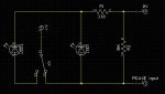
I have a 2-position switch (with 3 prongs similar to this but much much smaller). I want to detect the position of the switch with a single picaxe input pin. Also, I want one LED to illuminate if the switch is one direction, and a different LED to illuminate if the switch is in the other direction. I also want to prevent the input pin from floating. I want the circuit to be as simple as possible.


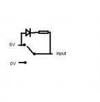
(the resistor between 5v and the switch is of a resistance that provides safe LED illumination)

Does this represent the easiest/simplest way to do such a thing? What type of resistance would be best for grounding the input pin? (I'm assuming higher than lower?) Does it really matter? Additionally, will this circuit reliably prevent a floating state? Is there a better way? I'm a newbie and I feel like I'm just tossing parts at this project without thinking it through properly...
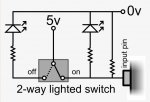
 
Last edited:

Dippy

Moderator
Just to 'amplify' on SS response re: "...input goes high enough to register."

For a PICAXE input to be 'seen' as High in code it MUST be above a certain threshold voltage. And for it to be 'seen' as Low it MUST be below a certain threshold voltage.

Manual 1 Page 7 states:
"An input should be above (0.8 x power supply voltage) to be high, below (0.2 x power
supply voltage) to be low."

- whilst more experienced people will point out that there are certain variations depending on input type, these figures can be considered as 'safe'.

It is worth absorbing these little sections of the Manual as it can prevent cockups at early stages.

(Once you are more comfortable with these things Andrew can explain the differences between PIC Input types and run through the semiconductors used.)
 

Andrew Cowan

Senior Member
(Once you are more comfortable with these things Andrew can explain the differences between PIC Input types and run through the semiconductors used.)
I can?

Well, I'm not sure what PICAXE your are using, but the high low voltages are below:
Hippy said:
Code:
TTL ( Vsupply > 4.5V )

Vih : >= 2.0V
Vil : <= 0.8V

TTL ( Vsupply <= 4.5V )

Vih : >= 0.25 * Vsupply + 0.8V
Vil : <= 0.15 * Vsupply

Schmitt Trigger (ST)

Vih : >= 0.8 * Vsupply ( >= 4V @ 5V )
Vil : <= 0.2 * Vsupply ( <= 1V @ 5V )

[B]
PICAXE-08 ( 12F629 )[/B]

Serial In TTL

In 1 TTL
In 2 ST
In 3 TTL
In 4 TTL

Vsupply = 2.2V to 5.5V ( 4MHz )


[B]PICAXE-08M ( 12F683 )[/B]

Serial In TTL

In 1 TTL
In 2 ST
In 3 TTL
In 4 TTL

Vsupply = 2.0V to 5.5V ( 4MHz, 8MHz )


PICAXE-14M ( 16F684 )

Serial In TTL

In 0 TTL
In 1 TTL
In 2 TTL
In 3 TTL
In 4 TTL

Vsupply = 2.0V to 5.5V ( 4MHz, 8MHz )

[B]
PICAXE-18 ( 16F627A )[/B]

Serial In ST

In 0 ST
In 1 ST
In 2 ST
In 6 ST
In 7 ST

Vsupply = 3.0V to 5.5V ( 4MHz )


[B]PICAXE-18A / PICAXE-18M ( 16F819 )[/B]

Serial In ST

In 0 TTL
In 1 TTL
In 2 TTL
In 6 ST
In 7 ST

Vsupply = 4.0V to 5.5V ( 4MHz, 8MHz )


[B]PICAXE-18X ( 16F88 )
[/B]
Serial In ST

In 0 TTL
In 1 TTL
In 2 TTL
In 6 ST
In 7 ST

Vsupply = 4.0V to 5.5V ( 4MHz, 8MHz )


[B]PICAXE-20M ( 16F677 )[/B]

Serial In TTL

In 0 TTL
In 1 ST
In 2 ST
In 3 ST
In 4 ST
In 5 ST
In 6 TTL
In 7 TTL

Vsupply = 2.0V to 5.5V ( 4MHz, 8MHz )

[B]
PICAXE-20X2 ( 18F14K22 )[/B]

Serial In TTL

C.0 TTL - B.0 TTL - A.0 TTL
C.1 ST - B.1 TTL
C.2 ST - B.2 ST
C.3 ST - B.3 ST
C.4 ST - B.4 ST
C.5 ST - B.5 TTL
C.6 TTL - B.6 TTL
C.7 TTL - B.7 TTL

Vsupply = 1.8V to 2.7V ( DC to 10MHz )
Vsupply = 1.8V to 3.6V ( DC to 64MHz )

[B]
PICAXE-28 / PICAXE-28A ( 16F872 )[/B]

Serial In ST

In 0 ST
In 1 ST
In 2 ST
In 3 ST
In 4 ST
In 5 ST
In 6 ST
In 7 ST

Vsupply = 4.0V to 5.5V ( DC to 20MHz )

[B]
PICAXE-28X ( 16F873A )[/B]

Serial In ST

In 0 ST - PortA 0 TTL
In 1 ST - PortA 1 TTL
In 2 ST - PortA 2 TTL
In 3 ST - PortA 3 TTL
In 4 ST
In 5 ST
In 6 ST
In 7 ST

Vsupply = 4.0V to 5.5V ( DC to 20MHz )

[B]
PICAXE-28X1 ( 16F886 )[/B]

Serial In TTL

In 0 ST - PortA 0 TTL
In 1 ST - PortA 1 TTL
In 2 ST - PortA 2 TTL
In 3 ST - PortA 3 TTL
In 4 ST
In 5 ST
In 6 ST
In 7 ST

Vsupply = 2.0V to 5.5V ( DC to 8MHz, internal resonator )
Vsupply = 4.5V to 5.5V ( DC to 20MHz, external resonator )


[B]PICAXE-28X2 ( 18F2420 )[/B]

Serial In ST

C.0 ST - B.0 TTL - A.0 TTL
C.1 ST - B.1 TTL - A.1 TTL
C.2 ST - B.2 TTL - A.2 TTL
C.3 ST - B.3 TTL - A.3 TTL
C.4 ST - B.4 TTL
C.5 ST - B.5 TTL
C.6 ST - B.6 TTL
C.7 ST - B.7 TTL

Vsupply = 4.2V to 5.5V ( DC to 40MHz )


[B]PICAXE-40X ( 16F874A )[/B]

Serial In ST

In 0 TTL - PortC 0 ST - PortA 0 TTL
In 1 TTL - PortC 1 ST - PortA 1 TTL
In 2 TTL - PortC 2 ST - PortA 2 TTL
In 3 TTL - PortC 3 ST - PortA 3 TTL
In 4 TTL - PortC 4 ST
In 5 TTL - PortC 5 ST
In 6 TTL - PortC 6 ST
In 7 TTL - PortC 7 ST

Vsupply = 4.0V to 5.5V ( DC to 20MHz )


[B]PICAXE-40X1 ( 16F887 )[/B]

Serial In TTL

In 0 TTL - PortC 0 ST - PortA 0 TTL
In 1 TTL - PortC 1 ST - PortA 1 TTL
In 2 TTL - PortC 2 ST - PortA 2 TTL
In 3 TTL - PortC 3 ST - PortA 3 TTL
In 4 TTL - PortC 4 ST
In 5 TTL - PortC 5 ST
In 6 TTL - PortC 6 ST
In 7 TTL - PortC 7 ST

Vsupply = 2.0V to 5.5V ( DC to 8MHz, internal resonator )
Vsupply = 4.5V to 5.5V ( DC to 20MHz, external resonator )


[B]PICAXE-40X2 ( 18F4420 )[/B]

Serial In ST

D.0 ST - C.0 ST - B.0 TTL - A.0 TTL
D.1 ST - C.1 ST - B.1 TTL - A.1 TTL
D.2 ST - C.2 ST - B.2 TTL - A.2 TTL
D.3 ST - C.3 ST - B.3 TTL - A.3 TTL
D.4 ST - C.4 ST - B.4 TTL
D.5 ST - C.5 ST - B.5 TTL - A.5 ST
D.6 ST - C.6 ST - B.6 TTL - A.6 ST
D.7 ST - C.7 ST - B.7 TTL - A.7 ST

Vsupply = 4.2V to 5.5V ( DC to 40MHz )
Not sure why this is relevent. The pullup resistor is not needed if the switch makes it either high or low.


A
 

Attachments

Andrew Cowan

Senior Member
Either a resistor or capacitor (to 0V or 5V) will stop the pin floating when the switch is in between positions. However, when it floats, it will be seen as either 1 or 0. When it is halfway between 0V and 5V, surely it doesn't matter if it displays a 1 or 0 during the switching time? Prehaps a slight debounce pause is needed.

A
 

jglenn

Senior Member
Normal LEDs will have 2V across them, which will be the logic high. That is too low. 2.5V is too low. 3V is marginal. Shoot for 5V input signals.
 

westaust55

Moderator
If the LED's are of different colours, they will have different forward voltage drops. So at the great expense of another resistor a better arranagement for LED brightness adjustment and correct PICAXE input signal level would/could be as per the attached:
 

Attachments

Ralpht

New Member
Either a resistor or capacitor (to 0V or 5V) will stop the pin floating when the switch is in between positions. However, when it floats, it will be seen as either 1 or 0. When it is halfway between 0V and 5V, surely it doesn't matter if it displays a 1 or 0 during the switching time? Prehaps a slight debounce pause is needed.
The Picaxe pin won't float because there is a resistor (nominal value of 4K7 - 10K ) always pulling the pin to gnd. It will always be seen a a "0" until the switch settles down in either position, after which it will see a "hi".

SS's circuit (or Westaust55's) is the best option so that a solid "hi" is presented to the Picaxe pin when the switch is in one position or the other.

When the switch contacts bounce the picaxe will see multiple lo - hi transitions till the bouncing stops. But never see a floating pin.

Why not use cross coupled Nand gated to stop bouncing and as a reliable indication of switch position? You can then drive something else from the Nand outputs as well. That's assuming you actually want this switch to do something other than just show the position of the switch.
 

SilentScreamer

Senior Member
Either a resistor or capacitor (to 0V or 5V) will stop the pin floating when the switch is in between positions. However, when it floats, it will be seen as either 1 or 0. When it is halfway between 0V and 5V, surely it doesn't matter if it displays a 1 or 0 during the switching time? Prehaps a slight debounce pause is needed.

A
The resistor stops it from floating, without it it will float and you'll get erratic results.
 
Top