Interface to zipzap car

jtbarclay

New Member
I'm trying to control a small micro rc car using picaxe. The car is driven by 4 mosfets that control forward, reverse, left and right. I plan on connecting 4 output pins to npn transistors to bring one leg of the mosfet high, and powering that motor. Is it possible to bring two output high at the same time so that I can go forward and left/right at the same time? Or is my best choice to just wire my turning transistors to forward and left or right and give up on being able to steer in reverse?

Thanks,
Jon
 

jodicalhon

New Member
It would help to have a schematic of the car's circuitry. Can you post one, or provide a link?

edit: Are the schematics on this page applicable to your car? If so, are your motors controlled by BJTs or FETs, i.e has your car been FET modded as per the link?
 
Last edited:

jtbarclay

New Member
Been there...done that!

The link to my posting in the User Projects - Robots forum: http://www.picaxeforum.co.uk/showthread.php?t=8598

This was for the low end ZipZap, the ones without proportional steering.

Ken
That is the same type of car I have it was just a cheap x-mas gift.

I had actually seen your thread earlier it helped a little although I'm just trying to control the actual vehicle and no use any of the radio circuit.

I did some more probing around and found some pins that when brought high trigger the motors and draw less than 5ma, unlike the other pins on the transistors that were drawing 150ma.

I am still wondering if it is possible to bring two of the output pins of a picaxe high at the same time, could someone post some sample code? Or if I will need to use 6 output pins to achieve F, B, FR, FL, BR, and BL? (forward, back, forward-right, etc.)

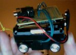
I tried to take some pictures of the circuit but it's just too small for my phone I will try to borrow a camera soon.

Thanks,
Jon
 

lbenson

Senior Member
>wondering if it is possible to bring two of the output pins of a picaxe high at the same time

With the "pins =" statement, you can bring 2 to 8 pins high with one instruction, depending on the PICAXE used. Hippy said, "Not sure about what's been quoted officially as to PICAXE execution but some earlier tests revealed about 2000 instructions per second at 4MHz" (here: http://www.picaxeforum.co.uk/showthread.php?t=2019 ). This would indicate that 2 or more outputs could be brought high within about 500 microseconds (although picaxe instruction timing is not exact). But even with two instructions, "high 1" followed by "high 2", two pins can be brought high in about a millisecond.

For some purposes, within 500 microseconds or within one millisecond would not be considered "at the same time", but for controlling an rc car, or a real car, it probably would be.
 

jtbarclay

New Member
>wondering if it is possible to bring two of the output pins of a picaxe high at the same time

With the "pins =" statement, you can bring 2 to 8 pins high with one instruction, depending on the PICAXE used. Hippy said, "Not sure about what's been quoted officially as to PICAXE execution but some earlier tests revealed about 2000 instructions per second at 4MHz" (here: http://www.picaxeforum.co.uk/showthread.php?t=2019 ). This would indicate that 2 or more outputs could be brought high within about 500 microseconds (although picaxe instruction timing is not exact). But even with two instructions, "high 1" followed by "high 2", two pins can be brought high in about a millisecond.

For some purposes, within 500 microseconds or within one millisecond would not be considered "at the same time", but for controlling an rc car, or a real car, it probably would be.
Thank you!

Still no package today. Has anyone dealt with http://www.world-educational-services.net/cart/ before?
 

lbenson

Senior Member
World Educational Services is within 100 miles of me. Sometimes I get second day service; sometimes it takes much longer. Everything has always arrived ultimately. For faster service, if he has the parts, I have always found PHAnderson to be very prompt--he's also near-local to me. JRHackett has also always been very prompt for me, and he's nearer to you if it matters. Both PHAnderson and JRHackett appear on the forum from time to time, and seem to sell their wares more to support hobbiests than as a business (tho of course I don't know their business model). Dr. Anderson teaches EE and has a site with a lot of picaxe information, tho he has drifted away. Mr. Hackett writes articles on the picaxe for Nuts and Volts magazine. I like dealing with individuals whose interests are in some degree known to me.
 

KMoffett

Senior Member
I did some more probing around and found some pins that when brought high trigger the motors and draw less than 5ma, unlike the other pins on the transistors that were drawing 150ma.
I can post a picture (Monday) of the connections to the transmitter PCB to enable F/B/L/R with a PICAXE through 4 NPN open-collector transistor inverters, as shown in my first schematic. Since it takes ~100mS to active the receiver outputs once the transmitter button is pushed, and considering the inertial lag in the car movement, as lbenson said, bringing two PICAXE outputs high, one after the other, is really simultaneous for your purposes.

Ken
 

KMoffett

Senior Member
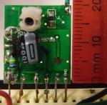
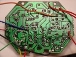
The attached are the output and input connections for my ZipZap. The receiver connections are clearly marked on the PCB. The transmitters inputs parallel the push button switches. These are the five wires dressed to the left [Green/Pink/Orange/Blue and Black(-)].

Ken
 

Attachments

KMoffett

Senior Member
If it has 4 pushbutton switches, my guess is it will work the same. What I did was (with batteries removed) connect one lead of an ohmmeter to the (-) terminal of the battery pack. Measure the continuity to each of the 4 terminals on each switch. The one of the two on each that change from open to short when press will be the ones you connect to an external circuit.

Ken
 
Top