Hi all.
I needed try to communicate via SPI. I choosed 16-Bit I/O Expander with SPI Interface for my HalloWorld. So, there is a simple example, how to use MCP23S17 via SPI. Circuit is connected according to Figure 1.
I am hoping, that it will be usefull for other people, which want to start communicate via SPI, or which need expand their ports.
Have a nice day")
Ps:
If it will read some PICAXE GURU, which will find any bug or big inefficiency, i will very happy if he tells me a new idea or corrections. If it will read english native speaker, and he will find some big grammar mistake, i will happy for correction too.
Program code:
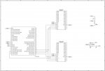
I needed try to communicate via SPI. I choosed 16-Bit I/O Expander with SPI Interface for my HalloWorld. So, there is a simple example, how to use MCP23S17 via SPI. Circuit is connected according to Figure 1.
I am hoping, that it will be usefull for other people, which want to start communicate via SPI, or which need expand their ports.
Have a nice day
Ps:
If it will read some PICAXE GURU, which will find any bug or big inefficiency, i will very happy if he tells me a new idea or corrections. If it will read english native speaker, and he will find some big grammar mistake, i will happy for correction too.
Program code:
Code:
;**************************************************
;AUTHOR: CAGI, DATE: 25.5.2012
;**************************************************
;PROGRAM DESCRIPTION:
;This program offer simple example, how to use
;16-Bit I/O Expander with SPI Interface. There
;are two MCP23S17 controled by 40X2. First of them
;(via cable select CS1) is set like an input. Second
;(via cable select CS2) is set like an output.
;Program transfer states from intput expander
;to output expander only. It help

;**************************************************
;PROCESSOR SETTING
	#PICAXE 40X2

;**************************************************
;CLOCK SETTING
;8MHz external oscilator (32MHz after PPL multiplying)
	setfreq em32

;**************************************************
;IO SETTING
;bits order:       %01234567;1=out, 0=in
	let dirsA =  %00000100
	let dirsD =  %00000000

;**************************************************
;DEFINITIONS
	symbol LED=A.5
	symbol CS1=D.3
	symbol CS2=D.2
	symbol IOCON=$0A
	symbol IODIRA=$00
	symbol IODIRB=$01
	symbol GPPUA=$0C
	symbol GPPUB=$0D
	symbol GPIOA=$12
	symbol GPIOB=$13
	symbol SPIwrite=%01000000	;bit7: write->R/W=0,read->R/W=1
	symbol SPIread=%01000001	;MCP23S17 address pins disabled
	symbol SPIdata=b0

;**************************************************
;SPI SETTING
	HSPISETUP spimode00, spifast
;Disabling sequential operation (automatic address inceremnting)
	low CS1
	hspiout (SPIwrite,IOCON)
	hspiout (%00100000)
	high CS1

	low CS2
	hspiout (SPIwrite,IOCON)
	hspiout (%00100000)
	high CS2
;Setting expander 1 like an input
	low CS1				;enable chip select
	hspiout (SPIwrite,IODIRA)	;choosing register to write
	hspiout (%11111111)		;data are clocked in to expander
	high CS1				;disable chip select

	low CS1
	hspiout (SPIwrite,IODIRB)
	hspiout (%11111111)
	high CS1
;Setting expander 2 like an output
	low CS2
	hspiout (SPIwrite,IODIRA)
	hspiout (%00000000)
	high CS2

	low CS2
	hspiout (SPIwrite,IODIRB)
	hspiout (%00000000)
	high CS2
;Enabling PullUp resistors at expamder 1
	low CS1
	hspiout (SPIwrite,GPPUA)
	hspiout (%11111111)
	high CS1

	low CS1
	hspiout (SPIwrite,GPPUB)
	hspiout (%11111111)
	high CS1

;**************************************************
;MAIN LOOP

main:
	toggle LED

	low CS1				;enable chip select
	hspiout (SPIread,GPIOA)		;choosing register to read
	hspiin (SPIdata)			;clocked out data from expander
	high CS1				;disable chip select

	low CS2
	hspiout (SPIwrite,GPIOA)
	hspiout (SPIdata)
	high CS2

	low CS1
	hspiout (SPIread,GPIOB)
	hspiin (b1)
	high CS1

	low CS2
	hspiout (SPIwrite,GPIOB)
	hspiout (b1)
	high CS2

	pause 100
	debug

	goto main

;**************************************************
;END