Hi All,
I built a small pot-box test jig recently.
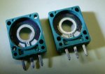
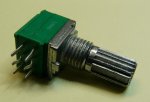
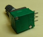
It has 8x 10K pots in the box, with all the pot-ends wired to 5v and 0v accordingly, then the 8x wipers connect to a 40X2 picaxe on all 8 bits of Port-D (set to analogue inputs).
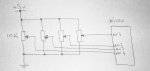
An older sketch of just 4 pots wired into my picaxe, just to clarify my wiring (x8):
While my test code works, there doesn't seem to be much physical range on my pots
I have a strong feeling that the 8x 10K pots (basically paralleled) has now made each pot appear as a 1.2k pot into the A-D pin.
Maybe i should raise all my pots to 50K so the final value is approx 6.2k, giving more voltage range across the pot movement?
(or 8x 100K pots, giving a 12.5k total).
I have used a quick 'lookup' code to test the concept.
Using the above code, the beginning of the pot rotation does nothing for about 10mm of rotation, then the lookup data starts appearing on my Port B LEDs.
At this time, basically each 1mm of pot movement will advance to the next lookup data, and after the last data is displayed, there's a further 10mm of travel before the pot reaches it's physical end point.
I thought that dividing the A-D range of 0-255 into 16 'zones' would spread quite evenly across the travel of the pot.
Even if i use 10bit ADC, it's the same effect with pot rotation not being spread out evenly.
I have then replaced the 'lookup' code with a 'select case' method (below), to create 16x evenly spaced pot 'zones', but the pot still bahaves the same way, all the action in the central area of the pot, but nothing on the ends.
I changed code to read each of the 8 pots, so i know the pot(s) aren't faulty, they all respond the same way.
Should i be using a different way to zone my pot range? or just replacing the pots to much higher values?
Thanks in advance...
I built a small pot-box test jig recently.
It has 8x 10K pots in the box, with all the pot-ends wired to 5v and 0v accordingly, then the 8x wipers connect to a 40X2 picaxe on all 8 bits of Port-D (set to analogue inputs).
An older sketch of just 4 pots wired into my picaxe, just to clarify my wiring (x8):
While my test code works, there doesn't seem to be much physical range on my pots
I have a strong feeling that the 8x 10K pots (basically paralleled) has now made each pot appear as a 1.2k pot into the A-D pin.
Maybe i should raise all my pots to 50K so the final value is approx 6.2k, giving more voltage range across the pot movement?
(or 8x 100K pots, giving a 12.5k total).
I have used a quick 'lookup' code to test the concept.
Code:
Symbol Pot_1 = b0
Symbol LEDPort = outpinsB

do

     readadc 20, Pot_1    ; Read Pot#1 connected to the Port D.0 pin
     Pot_1=Pot_1/16    ; divide pot into ranges of "16" (256/16='16' zones of the physical pot rotation where each value will change.
     lookup Pot_1,($00,$08,$04,$02,$01,$0C,$06,$03,$09,$0A,$05,$0E,$07,$0B,$0D,$0F),LEDport    ;Load value into LEDport for the testing on some LEDS.

loopAt this time, basically each 1mm of pot movement will advance to the next lookup data, and after the last data is displayed, there's a further 10mm of travel before the pot reaches it's physical end point.
I thought that dividing the A-D range of 0-255 into 16 'zones' would spread quite evenly across the travel of the pot.
Even if i use 10bit ADC, it's the same effect with pot rotation not being spread out evenly.
I have then replaced the 'lookup' code with a 'select case' method (below), to create 16x evenly spaced pot 'zones', but the pot still bahaves the same way, all the action in the central area of the pot, but nothing on the ends.
I changed code to read each of the 8 pots, so i know the pot(s) aren't faulty, they all respond the same way.
Should i be using a different way to zone my pot range? or just replacing the pots to much higher values?
Thanks in advance...
Code:
select case Pot_1

    case 0 to 15            ; if "Pot_Speed" value is within this range, then
        LEDport = $00        ;output this data on Cport LSB 4 bits to LEDs
    case 16 to 31            ; if "Pot_Speed" value is within this range, then
        LEDport = $08        ;output this data on Cport LSB 4 bits to LEDs
    case 32 to 47            ; if "Pot_Speed" value is within this range, then
        LEDport = $04        ;output this data on Cport LSB 4 bits to LEDs
    case 48 to 63            ; if "Pot_Speed" value is within this range, then
        LEDport = $02        ;output this data on Cport LSB 4 bits to LEDs
    case 64 to 79            ; if "Pot_Speed" value is within this range, then
        LEDport = $01        ;output this data on Cport LSB 4 bits to LEDs
    case 80 to 95            ; if "Pot_Speed" value is within this range, then
        LEDport = $0C        ;output this data on Cport LSB 4 bits to LEDs
    case 96 to 111            ; if "Pot_Speed" value is within this range, then
        LEDport = $06        ;output this data on Cport LSB 4 bits to LEDs
    case 112 to 127            ; if "Pot_Speed" value is within this range, then
        LEDport = $03        ;output this data on Cport LSB 4 bits to LEDs
    case 128 to 143            ; if "Pot_Speed" value is within this range, then
        LEDport = $09        ;output this data on Cport LSB 4 bits to LEDs
    case 144 to 159            ; if "Pot_Speed" value is within this range, then
        LEDport = $0A        ;output this data on Cport LSB 4 bits to LEDs
    case 160 to 175            ; if "Pot_Speed" value is within this range, then
        LEDport = $05        ;output this data on Cport LSB 4 bits to LEDs
    case 176 to 191            ; if "Pot_Speed" value is within this range, then
        LEDport = $0E        ;output this data on Cport LSB 4 bits to LEDs
    case 192 to 207            ; if "Pot_Speed" value is within this range, then
        LEDport = $07        ;output this data on Cport LSB 4 bits to LEDs
    case 208 to 223            ; if "Pot_Speed" value is within this range, then
        LEDport = $0B        ;output this data on Cport LSB 4 bits to LEDs
    case 224 to 239            ; if "Pot_Speed" value is within this range, then
        LEDport = $0D        ;output this data on Cport LSB 4 bits to LEDs
    case 240 to 255            ; if "Pot_Speed" value is within this range, then
        LEDport = $0F        ;output this data on Cport LSB 4 bits to LEDs


    endselect
Last edited: