Hairy Animal
Member
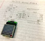
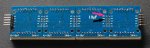
This project aims to display a message of about 18 (or more if required) alphanumeric characters on four 8x8 LED matrix displays (i.e. 32x8 pixels) using pixel by pixel (column by column) scrolling.
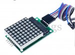
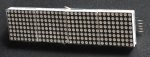
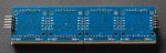
The hardware in use is (four off) the FC-16 board & display shown in the attached pictures, which are available from a well known internet auction site for less than £0.89 (yes really!) per board complete with soldered MAX7219 and the LED matrix display (price when bought as three sets of four boards).
For minimal cost and simplicity a PICAXE-08M2 is used as the controller but the more sophisticated -X2 processors can work faster if a higher speed is required.
The overall cost (excluding PCB & PSU) is about £5 (UKP) at 2019 prices.
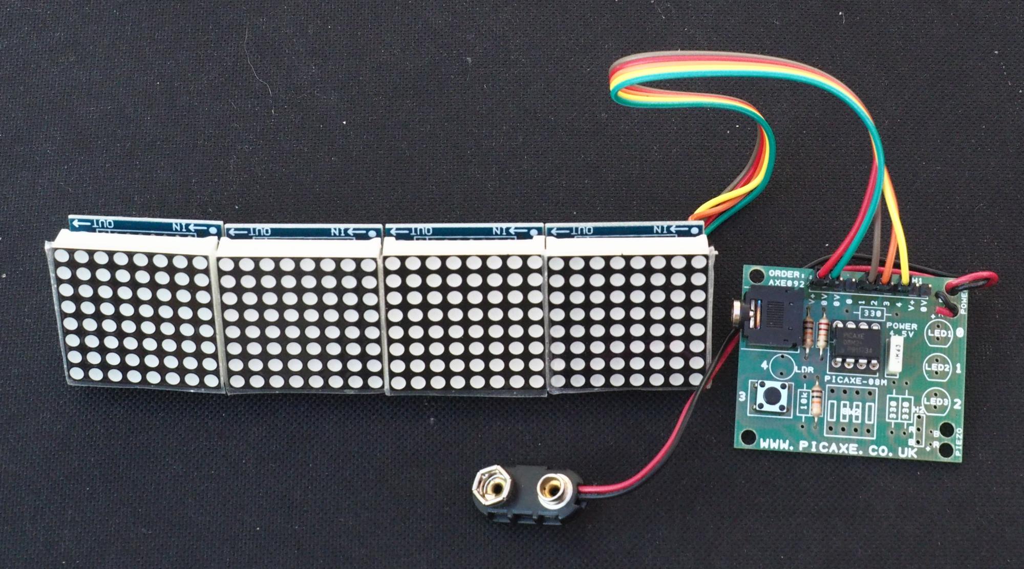
Firstly, some notes about the hardware. The FC-16 board (normally blue in colour) can be bought in various kit forms:
The latter is very convenient for this project as it should connect simply to the three relevant pins on the 08M2 with minimal extra hardware. The first on the list is only suitable if you have an extremely fine soldering iron, a very good magnifying glass, three or four hands, and can position components to within about 1/20th of a millimetre.
There are also other similar boards available which I haven't tested and may not be suitable:
The former may not work because the orientation of the matrix displays when assembled side-by-side to make a continuous display looks as though it's 90° rotated compared to the boards used in this project. It may well be usable as a multi-character display but the software would need significant changes.
The latter may be suitable as the LED display seems to have the right orientation, but would need to be tested.
If assembling/soldering these (blue FC-16) boards yourself (kits without the connectors & sockets soldered), firstly check the correct location for the sockets for the LED displays. The sockets are on the same side as the MAX7219 therefore soldered from the other side. To ensure the sockets are exactly square to the PCB, push the sockets carefully onto the pins of the LED array then insert the sockets into the PCB (covering the MAX7219) and solder one pin on each socket. Check that it all looks square before soldering the rest - you could easily desolder one pin on each side if it's wrong but more than one gets very difficult.

The display then needs to be carefully removed (so as not to bend the pins) before soldering the pin headers. A similar principle applies; solder one pin and check for correct positioning before soldering the rest of the pins. Note that the distance between the two headers is not a multiple of 0.1" so Veroboard or similar can't be used to hold the headers in place.
When all the headers and sockets are soldered, the LED matrix display needs to be reinserted in its sockets. Obviously there are two ways it could be put, this is the right way:
The 5 volt supply needs to be capable of supplying at least 700mA - this is what the four displays etc take when all 32 x 8 LEDs are full on during the display test at maximum brightness. However, this is probably on the limit of the power dissipation of the MAX7219 devices. The RSET resistor (R1 in above picture) on the boards is 10k which, with the VLED (forward LED voltage) of about 1.8V, sets a peak segment current of more than 40mA. It would not be a good idea to leave the display with all LEDs on at maximum brightness for a long time. See the Maxim MAX7219 data sheet for more detailed information.
For optimum long term reliability it would probably be better (with the given displays) to change the RSET value to 12k for 40mA (ISEG current), 18k for about 28mA or 39k for approximately 15mA. The ambient light level the display is used in will determine how bright the displays need to be - there's a very big difference between needing to be seen in bright sunlight or a dimly lit room.
In operation with the hardware and software as shown, the current varies between about 30mA with no LEDs on, to 50 - 60mA with many characters on the display. The software sets the brightness to 3/32 of the peak segment current which still gives a very bright display. Setting higher values than this will obviously take more current.
The software has been written using elements of WestAus55's helpful tutorial on the MAX7219 and Hippy's excellent routines from the Active PicAxe forum together with my own display routines.
In the latter thread are other examples of code to do the same things on other PICAXE processors and in more versatile ways. The code here is limited to four 8 x 8 LED displays and could be adapted to a smaller display but not larger.
I've tried to put plenty of comments in the code by way of explanation but such things can always be improved.
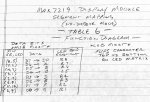
In addition to the code is a complete set of alphanumeric characters from which to build up a new message. It should be fairly obvious how these are used from looking at the example. Note that each character has an inter-character space at the end which needs to be preserved. Longer characters can easily be constructed if required as could 'smileys' and similar.
Here is what it looks like when running:
The hardware in use is (four off) the FC-16 board & display shown in the attached pictures, which are available from a well known internet auction site for less than £0.89 (yes really!) per board complete with soldered MAX7219 and the LED matrix display (price when bought as three sets of four boards).
For minimal cost and simplicity a PICAXE-08M2 is used as the controller but the more sophisticated -X2 processors can work faster if a higher speed is required.
The overall cost (excluding PCB & PSU) is about £5 (UKP) at 2019 prices.
Firstly, some notes about the hardware. The FC-16 board (normally blue in colour) can be bought in various kit forms:
- all the parts completely unassembled;
- all the parts with the surface-mount (SM) components soldered;
- fully assembled boards;
- four off fully assembled boards.
The latter is very convenient for this project as it should connect simply to the three relevant pins on the 08M2 with minimal extra hardware. The first on the list is only suitable if you have an extremely fine soldering iron, a very good magnifying glass, three or four hands, and can position components to within about 1/20th of a millimetre.
There are also other similar boards available which I haven't tested and may not be suitable:
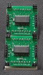
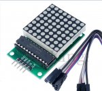
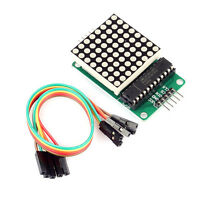
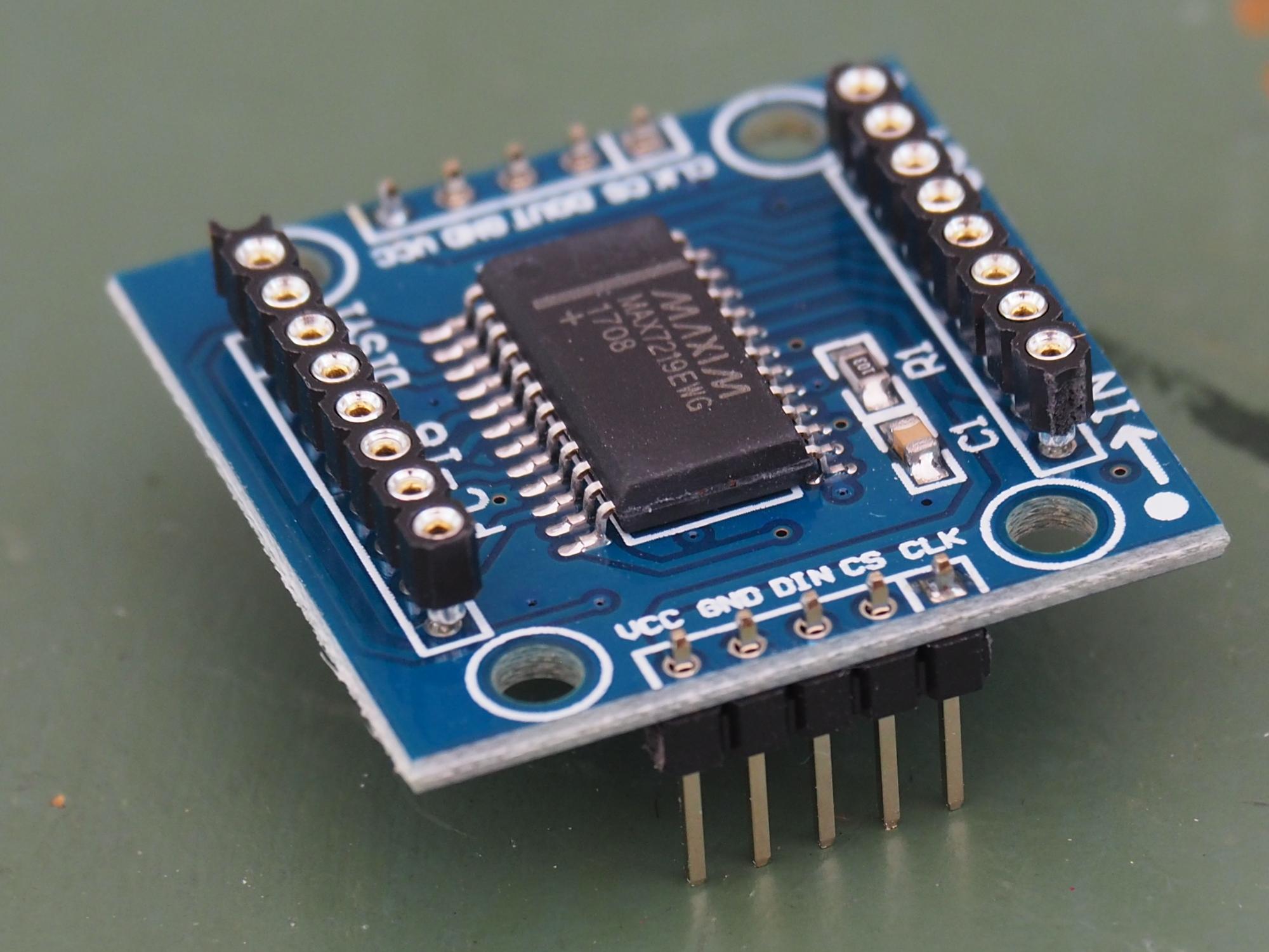
- a green PCB with a DIL 24-pin MAX7219 in a socket outside the matrix display area on the PCB (see below);
- a red/orange or green PCB with SM MAX7219 and four extra pairs of 2-pin headers in the corners (see previous image lower left).
The former may not work because the orientation of the matrix displays when assembled side-by-side to make a continuous display looks as though it's 90° rotated compared to the boards used in this project. It may well be usable as a multi-character display but the software would need significant changes.
The latter may be suitable as the LED display seems to have the right orientation, but would need to be tested.
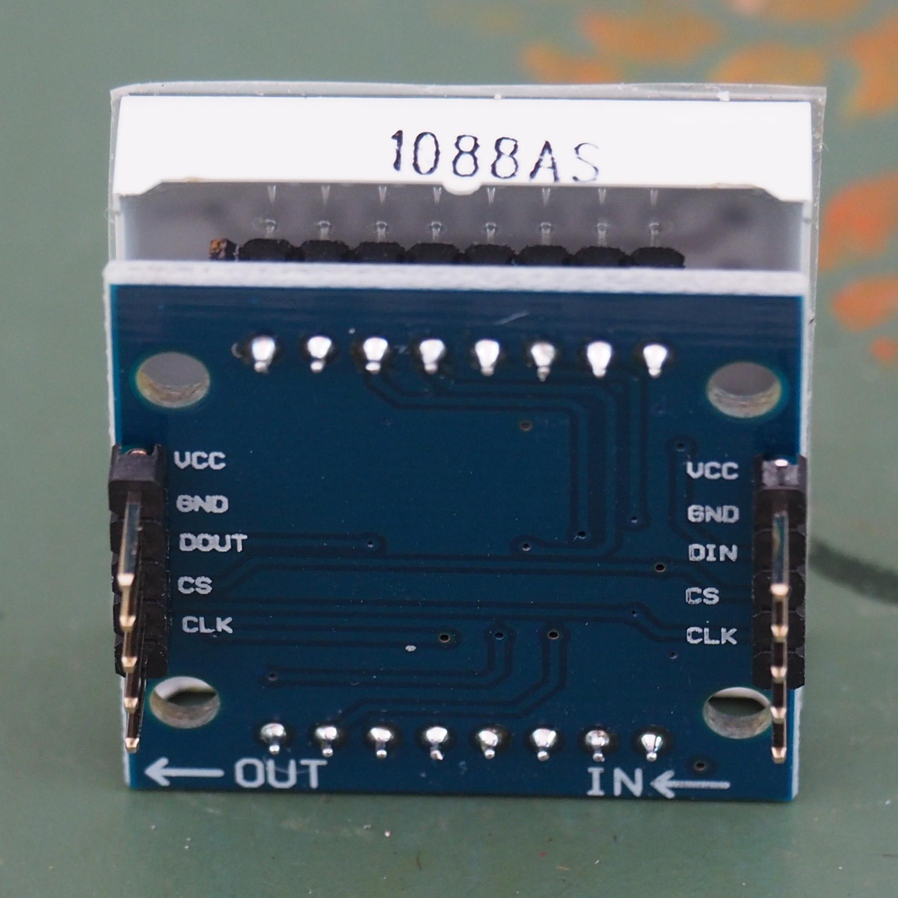
If assembling/soldering these (blue FC-16) boards yourself (kits without the connectors & sockets soldered), firstly check the correct location for the sockets for the LED displays. The sockets are on the same side as the MAX7219 therefore soldered from the other side. To ensure the sockets are exactly square to the PCB, push the sockets carefully onto the pins of the LED array then insert the sockets into the PCB (covering the MAX7219) and solder one pin on each socket. Check that it all looks square before soldering the rest - you could easily desolder one pin on each side if it's wrong but more than one gets very difficult.
The display then needs to be carefully removed (so as not to bend the pins) before soldering the pin headers. A similar principle applies; solder one pin and check for correct positioning before soldering the rest of the pins. Note that the distance between the two headers is not a multiple of 0.1" so Veroboard or similar can't be used to hold the headers in place.
When all the headers and sockets are soldered, the LED matrix display needs to be reinserted in its sockets. Obviously there are two ways it could be put, this is the right way:
The 5 volt supply needs to be capable of supplying at least 700mA - this is what the four displays etc take when all 32 x 8 LEDs are full on during the display test at maximum brightness. However, this is probably on the limit of the power dissipation of the MAX7219 devices. The RSET resistor (R1 in above picture) on the boards is 10k which, with the VLED (forward LED voltage) of about 1.8V, sets a peak segment current of more than 40mA. It would not be a good idea to leave the display with all LEDs on at maximum brightness for a long time. See the Maxim MAX7219 data sheet for more detailed information.
For optimum long term reliability it would probably be better (with the given displays) to change the RSET value to 12k for 40mA (ISEG current), 18k for about 28mA or 39k for approximately 15mA. The ambient light level the display is used in will determine how bright the displays need to be - there's a very big difference between needing to be seen in bright sunlight or a dimly lit room.
In operation with the hardware and software as shown, the current varies between about 30mA with no LEDs on, to 50 - 60mA with many characters on the display. The software sets the brightness to 3/32 of the peak segment current which still gives a very bright display. Setting higher values than this will obviously take more current.
The software has been written using elements of WestAus55's helpful tutorial on the MAX7219 and Hippy's excellent routines from the Active PicAxe forum together with my own display routines.
In the latter thread are other examples of code to do the same things on other PICAXE processors and in more versatile ways. The code here is limited to four 8 x 8 LED displays and could be adapted to a smaller display but not larger.
I've tried to put plenty of comments in the code by way of explanation but such things can always be improved.
In addition to the code is a complete set of alphanumeric characters from which to build up a new message. It should be fairly obvious how these are used from looking at the example. Note that each character has an inter-character space at the end which needs to be preserved. Longer characters can easily be constructed if required as could 'smileys' and similar.
Here is what it looks like when running:
Attachments
-
12.7 KB Views: 18
-
6.1 KB Views: 19
Last edited: