lbenson
Senior Member
I've been looking at a backup water system for my house to provide water from my shallow well in case the electricity goes out. I had been thinking about a 12V pumping system, but then after mulling over how to get the water where I wanted it, it seemed to me easier to just provide backup to the 120V mains by putting what I want to keep running (pump, fridge, freezer) on a separate branch with a transfer switch to automatically switch over if mains goes out.
The battery or battery bank would be charged by solar with a trickle charger from mains. I'm looking at the Windy Nation 2-100 Watt panel kit with P20L controller.
https://www.windynation.com/Polycrystalline-Solar-Kits/WindyNation-Inc/Complete-200-Watt-Solar-Panel-Kit-with-1500W-VertaMax-Power-Inverter-for-12-Volt-Battery-Systems/-/362?p=YzE9NDY=
https://www.windynation.com/cm/Complete_Solar_Kit_Manual_R2.1.pdf
and https://www.windynation.com/cm/P20L Controller Manual_R1.pdf
I have a 100Ah battery and plan to get a 1500W pure sine wave inverter.
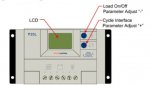
The controller will shut off solar charging above 13.8V and load below 10.7V (both settable). After the load is turned off, it will restart if the battery voltage reaches 12.6 (also settable). The controller takes 6 wires--two from the panels, two to the load, and two to/from the battery.
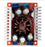
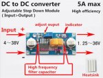
I plan to inject mains trickle charging at the battery terminals, using a 5A DC-DC buck regulator set at 13.8V with a 7.5-amp MBR745G Schottky diode and an appropriate current-limiting resistor.
I had thought I would use a picaxe to provide low-voltage cutout, but with these components, especially the controller and transfer switch, it seems to me that these parts are "self-leveling".
My main question is about an appropriate value for the current-limiting resistor. Since the controller assures that the load is disconnected if the battery voltage drops below (say) 10.7, the maximum difference between the buck regulator and the battery is 13.8-10.7 or 3.1 volts. With a 2-ohm resistor, that would be 3.1/2 or 1.55 amps (times 3.1 equals 4.81 watts). Is my math correct?
4.8 watts sounds like a lot for a 5W resistor, even with heat sinking. If there are 2 1-ohm 5W resistors in series, does that cut the heat in half for each? Or do I need 10W resistors.
I haven't done a complete analysis to make sure to not overload the inverter, but I think if I can make sure that the freezer and fridge don't run at the same time, I'll be fine. On a normal day, the water pump may run 10-12 times for 40 seconds--not many amp-hours in total.
Does this make sense?
The battery or battery bank would be charged by solar with a trickle charger from mains. I'm looking at the Windy Nation 2-100 Watt panel kit with P20L controller.
https://www.windynation.com/Polycrystalline-Solar-Kits/WindyNation-Inc/Complete-200-Watt-Solar-Panel-Kit-with-1500W-VertaMax-Power-Inverter-for-12-Volt-Battery-Systems/-/362?p=YzE9NDY=
https://www.windynation.com/cm/Complete_Solar_Kit_Manual_R2.1.pdf
and https://www.windynation.com/cm/P20L Controller Manual_R1.pdf
I have a 100Ah battery and plan to get a 1500W pure sine wave inverter.
The controller will shut off solar charging above 13.8V and load below 10.7V (both settable). After the load is turned off, it will restart if the battery voltage reaches 12.6 (also settable). The controller takes 6 wires--two from the panels, two to the load, and two to/from the battery.
I plan to inject mains trickle charging at the battery terminals, using a 5A DC-DC buck regulator set at 13.8V with a 7.5-amp MBR745G Schottky diode and an appropriate current-limiting resistor.
I had thought I would use a picaxe to provide low-voltage cutout, but with these components, especially the controller and transfer switch, it seems to me that these parts are "self-leveling".
My main question is about an appropriate value for the current-limiting resistor. Since the controller assures that the load is disconnected if the battery voltage drops below (say) 10.7, the maximum difference between the buck regulator and the battery is 13.8-10.7 or 3.1 volts. With a 2-ohm resistor, that would be 3.1/2 or 1.55 amps (times 3.1 equals 4.81 watts). Is my math correct?
4.8 watts sounds like a lot for a 5W resistor, even with heat sinking. If there are 2 1-ohm 5W resistors in series, does that cut the heat in half for each? Or do I need 10W resistors.
Code:
.___________.       .____________.      .____________.
|           | ~15V  |            | ~13V |            |
| 200W, 12V |-------|   P20L     |------|  Inverter  |
| Solar     |       | Controller |      |            |
| Panel     |-------|            |------|            |
|           |  0V   |            |  0V  |            |
'-----------'       '------------'      '------------'
                       |      |               | 120VAC              Load
.___________.          |      |         .____________.         .____________.
|           | ~13V8    |      |         |            |         |            |
| DC-DC reg |----------o      |         |  Transfer  |  120VAC |    Pump    |
| Diode     |          |      |         |   Switch   |---------|   Fridge   |
| Resistor  |----------|------o         |            |         |   Freezer  |
|           |  0V      |      |         |            |         |            |
'-----------'          |      |         '------------'         '------------'
                       |      |               | 120VAC
                     .____________.      .____________.
                     |            |      |            |
                     |   Battery  |      |            |
                     |    100Ah   |      |   Mains    |
                     |            |      |            |
                     |            |      |            |
'------------' '------------'Does this make sense?
Last edited: