Hi all, apologies if this has been cleared up in a previous thread I have searched but are still having problems.
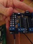
I have recently purchased the AXE133 Serial LCD for use in my project at college. I have followed the instructions and soldered the LCD as advised.
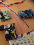
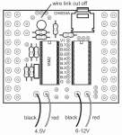
I am using a CHI030B 18M2 Project Board which I am powering through a 5V PSU which is connected to my breadboard.
Using the H2 connections on the LCD, I am connecting the V+ and 0V to the power rails of the breadboard, this is also shared with the Project Board.
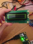
Rightly saying as the LCD is powered up I should see a welcome message, regardless if it is receiving and output or any code from the Project Board.... which I am not.
I have checked the respective voltages and tried to alter the 10K contrast potentiometer, when I turn the contrast up full I see black rectangles.
At first I entered this simple program to read hello, however I changed the output pin used from B.7 to C.7 due to the Darlington Chip array on the Project Board.
init: pause 500 ; wait for display to initialise
main:
serout C.7,N2400,(254,128) ; move to start of first line
serout C.7,N2400,("Hello!123") ; output text
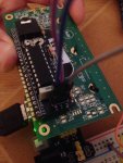
At the first attempt I downloaded the data to the 18M2 on the project board using the USB jack. To no avail, I inserted the USB jack into the LCD and tried to download the program to the 18M2 on the LCD which downloads successfully, suggesting correct positioning of the 18M2. Still nothing. I think I may have overwritten the code of the welcome message but should still see the Hello message.
Am I missing something major? Apologies again if this has already been cleared up as I am a newbie to Picaxe. I look forward to hearing from you.
Thanks a lot in advance.
Steven
I have recently purchased the AXE133 Serial LCD for use in my project at college. I have followed the instructions and soldered the LCD as advised.
I am using a CHI030B 18M2 Project Board which I am powering through a 5V PSU which is connected to my breadboard.
Using the H2 connections on the LCD, I am connecting the V+ and 0V to the power rails of the breadboard, this is also shared with the Project Board.
Rightly saying as the LCD is powered up I should see a welcome message, regardless if it is receiving and output or any code from the Project Board.... which I am not.
I have checked the respective voltages and tried to alter the 10K contrast potentiometer, when I turn the contrast up full I see black rectangles.
At first I entered this simple program to read hello, however I changed the output pin used from B.7 to C.7 due to the Darlington Chip array on the Project Board.
init: pause 500 ; wait for display to initialise
main:
serout C.7,N2400,(254,128) ; move to start of first line
serout C.7,N2400,("Hello!123") ; output text
At the first attempt I downloaded the data to the 18M2 on the project board using the USB jack. To no avail, I inserted the USB jack into the LCD and tried to download the program to the 18M2 on the LCD which downloads successfully, suggesting correct positioning of the 18M2. Still nothing. I think I may have overwritten the code of the welcome message but should still see the Hello message.
Am I missing something major? Apologies again if this has already been cleared up as I am a newbie to Picaxe. I look forward to hearing from you.
Thanks a lot in advance.
Steven