Higher Wattage 12v Card LED strobe unit
- Thread starter itolond
- Start date
controller = picaxe unitYou did not mention a "controller" before. Better give some more details so that the proper recommendations can be made.
Perhaps post a diagram of what you currently have.
Last edited:
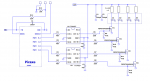
Attached is a example diagram of how I would do it. I have used Dual Mosfet drivers and low RDSOn FETS. This gives superior performance and efficiency.
However, if you only need to turn the LED's on and off occasionally then you can get by without the Mosfet drivers and can use Logic Level FETs driven directly from the Picaxe via a 330R resistor.
However, if you only need to turn the LED's on and off occasionally then you can get by without the Mosfet drivers and can use Logic Level FETs driven directly from the Picaxe via a 330R resistor.
Last edited:
Also are you just wanting ON/OFF function or dimming features?
I will us a carling rocker in vehicle to for on off, No dimming- just a strobe on /off situation
Great thanks - I will (may) need for short bursts or extended periods of time, so the later is the best optionAttached is a example diagram of how I would do it. I have used Dual Mosfet drivers and low RDSOn FETS. This gives superior performance and efficiency.
However, if you only need to turn the LED's on and off occasionally then you can get by without the Mosfet drivers and can use Logic Level FETs driven directly from the Picaxe via a 330R resistor.
View attachment 18818
inglewoodpete
Senior Member
I think you need to give us more details of the LEDs. Can you give a part/model number or a URL to the LED or data sheet? Goeytex has drawn each of them as a simple, single LED in the diagram. They will definitely not be that simple at 10 watts each!
10 watt LEDs come in many varieties and some can require nearly 1 Amp. If they are a bare 10W LED emitter, you need to consider current limiting otherwise they will quickly overheat and destroy themselves.
10 watt LEDs come in many varieties and some can require nearly 1 Amp. If they are a bare 10W LED emitter, you need to consider current limiting otherwise they will quickly overheat and destroy themselves.
IWP is correct. There likely needs to be current limiting of some kind. How this is implemented depends upon the 10 Watt LED Arrays.
My assumption was that since the OP had previous success with 6 watt units, that the need for current limiting was understood. I will add a current limit block to the diagram to eliminate any confusion.
Warning: Automotive electrical systems can generate transients > 60V. In automotive applications it is good design practice to use automotive grade regulator(s)/ components and to provide transient suppression devices such as TVS Diodes to protect the Picaxe and other components from these transient voltage spikes. Failure to do so could lead to failed components.
Failure to provide proper current limiting to the LEDs will result in overheating and failure of the LEDs. The previously attached circuit will not provide a constant current to the LED's over the range of the automobiles +12V supply. (12v - 13.5v)
A much better solution would be to use a constant current source or a commercial LED controller for driving the LEDs.
Last edited:
techElder
Well-known member
I don't know why anyone would still be using a resistor to limit the current in an LED circuit.
I am a fan of these constant current gadgets, and have used them so many times.
I use this variety: http://www.mouser.com/ProductDetail/Microchip-Technology/CL2N3-G/?qs=sGAEpiMZZMsE420DPIasPsmbGP/Dsdbv7CfbaiDKVaw=
This is a listing of many ways these are available: http://www.mouser.com/Search/Refine.aspx?Keyword=cl2+constant
EDIT: Sorry, I forgot the OP was looking at 10W LEDs. However, while I have your attention, these constant current drivers can easily be put in parallel to multiply the total current they provide.")
I am a fan of these constant current gadgets, and have used them so many times.
I use this variety: http://www.mouser.com/ProductDetail/Microchip-Technology/CL2N3-G/?qs=sGAEpiMZZMsE420DPIasPsmbGP/Dsdbv7CfbaiDKVaw=
This is a listing of many ways these are available: http://www.mouser.com/Search/Refine.aspx?Keyword=cl2+constant
EDIT: Sorry, I forgot the OP was looking at 10W LEDs. However, while I have your attention, these constant current drivers can easily be put in parallel to multiply the total current they provide.
Last edited:
With a nominal supply (battery) voltage of 12.5v and the LM317s 3.0V drop out voltage, the LM317 can only supply about 9.5V to the load. This may not be enough for the LED's.
An LM1086 (better) has a typical dropout voltage of 1.3V and might get close enough. It all depends on the LED's forward voltage.
An LM1086 (better) has a typical dropout voltage of 1.3V and might get close enough. It all depends on the LED's forward voltage.