READADC10 Bias

josefvs

New Member
Hi all,

I am trying to build a controller using a joystick.

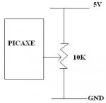
My problem is that using READADC10 or READADC I can't get a mid reading when the potential divider wiper is in the center position, the reading is significantly high using either commands.

I have also tried a hall effect sensor where it reads 2.5V when in the center.

All photometers I used have rail voltage applied (5V & 0) and show perfect half resistance in the mid position.

What am I doing wrong?

Thanks
 

hippy

Technical Support
Staff member
Double-check that you are actually reading the pot's wiper and don't have the pot mis-wired so its wiper is to 0V or 5V.

If you have a meter you can measure the wiper / PICAXE input pin voltage against 0V. What voltage does that show for mid-position and what does READADC / READADC10 readings give ?

You can also test using the mid-point of two 1K resistors across 0V/5V instead of the pots.
 

geoff07

Senior Member
Check the potentiometer impedance isn't too high. The ADC doesn't want to see more than 10k otherwise it doesn't have time to charge properly. There is only one ADC in the chip, multiplexed between all the ADC inputs, so the spec is a bit demanding.
 

nick12ab

Senior Member
  • What is your code?
  • Is the PICAXE powered by the same 5V power supply?
  • Have you set the ADC reference to something other than the power supply rails?
  • How high is 'significantly high'?
  • Does the readadc reading immediately start to rise from 0 when the voltage is slowly increased from 0V and immediately start to fall from 255 when the voltage is slowly reduced from 5V?
  • Do you have decoupling capacitors fitted?
  • If it is a PICAXE with more than one power pin per rail, are they all connected?
 

Dippy

Moderator
The drawing is a little light on info. More detail would help.
In addition to Nick's qs; can you confirm the grounds are definitely connected? (Joystick & PICAXE circuit).
 

hippy

Technical Support
Staff member
And what exactly is the "PICAXE" in the diagram ? If it's on a project board it could be that there are pull-up or pull-down resistors which are affecting the linearity of the pot.

The more info you can provide the better people will be able to guess why it's not working as expected.
 

AllyCat

Senior Member
Hi,

Are you sure it's a "Linear" and not a "Log" pot (as often used for volume controls)?

However that would normally give a low voltage at its centre; but what do you measure if the connections to the "end" terminals (Gnd/Vcc) are exchanged?

Cheers, Alan.
 
Top