Hello again.
This is the carry-on of the "readadc accuracy" thread although I doubt it will be as humorous as most of the carry-ons.
The problem at hand is trying to get a PICAXE to communicate with an accelerometer via I2C. The accelerometer does work, or at least I'm 99% sure it works, as it is the 2nd one I've bought and gives the same results. Also, this type of accel can be read using analogue outputs (hence the previous thread's name) and those work fine.
This is the datasheet for the accelerometer.
As for the code; The most successful code "on the market" at the moment is this:
This however (as you'd imagine) doesn't work. The data transaction to read from the accelerometer should go like this:
however this is what seems to be happening:
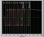
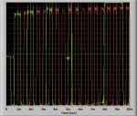
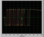
See the first attachment for a scope trace of the two lines.
I've tried using an EEPROM chip instead, and managed to get that working with similar code.
Because the accel is not acknowledging, the slave address must be wrong. Therefore, I decided to try ever possible slave address before I came back. This took a while to write out because, for some reason I cant use a variable as the slave address and simply increment it. Therefore I had to write out 128 addresses (the last bit is zero so 128 not 256). With the above code, I received "255" repeatedly. When I tried with each slave address, I didn't get any response except "RESET" over an over.
This is very strange because at the end of the code, I put the "end" command at the end of the code, so it should repeat the "RESET". I've attached the code for this. During this code, there doesn't seem to be any activity on the I2C lines (using th scope) so I assume there must be something wrong with the code.
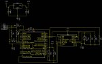
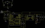
I'll try to get a Diptrace of the circuit together, but I still have to install diptrace on my recently wiped computer.
The description of it though is this:
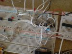
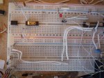
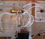
PICAXE28X2 connected up in normal way (breadboard)
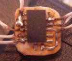
Accelerometer soldered onto it's own board with the correct SCL and SDA line connected to the PICAXE with 4k7 pull-ups.
ADDR on the accel is held high.
Enable on the accel is connected to B.5 on the PICAXE.
MOT enable on the accel is connected to B.4 on the PICAXE
FF/MOT interrupt on the accel is connected to an LED (the LED flashes if I tap the accel; more proof the accel works).
Thanks in advance as usual and sorry about pre-post.
David.
This is the carry-on of the "readadc accuracy" thread although I doubt it will be as humorous as most of the carry-ons.
The problem at hand is trying to get a PICAXE to communicate with an accelerometer via I2C. The accelerometer does work, or at least I'm 99% sure it works, as it is the 2nd one I've bought and gives the same results. Also, this type of accel can be read using analogue outputs (hence the previous thread's name) and those work fine.
This is the datasheet for the accelerometer.
As for the code; The most successful code "on the market" at the moment is this:
Code:
		#PICAXE28X2
pause 1000
high B.5
high B.4
pause 1000
setfreq m1

		i2cslave %00110010,255,i2cbyte

		let b1 = 0
		SERTXD("RESET")

main:		pause 50
		readi2c 3,(b0)
		sertxd (#b0,",")
		goto main
Code:
Master:                        S0011001W 00000011 S0011001R         NAP
Slave:                                  A        A         AXXXXXXXX
Code:
Master:                        S0011001W
Slave:I've tried using an EEPROM chip instead, and managed to get that working with similar code.
Because the accel is not acknowledging, the slave address must be wrong. Therefore, I decided to try ever possible slave address before I came back. This took a while to write out because, for some reason I cant use a variable as the slave address and simply increment it. Therefore I had to write out 128 addresses (the last bit is zero so 128 not 256). With the above code, I received "255" repeatedly. When I tried with each slave address, I didn't get any response except "RESET" over an over.
This is very strange because at the end of the code, I put the "end" command at the end of the code, so it should repeat the "RESET". I've attached the code for this. During this code, there doesn't seem to be any activity on the I2C lines (using th scope) so I assume there must be something wrong with the code.
I'll try to get a Diptrace of the circuit together, but I still have to install diptrace on my recently wiped computer.
The description of it though is this:
PICAXE28X2 connected up in normal way (breadboard)
Accelerometer soldered onto it's own board with the correct SCL and SDA line connected to the PICAXE with 4k7 pull-ups.
ADDR on the accel is held high.
Enable on the accel is connected to B.5 on the PICAXE.
MOT enable on the accel is connected to B.4 on the PICAXE
FF/MOT interrupt on the accel is connected to an LED (the LED flashes if I tap the accel; more proof the accel works).
Thanks in advance as usual and sorry about pre-post.
David.
Attachments
-
 48 KB Views: 36
 -
11.2 KB Views: 16
Last edited: